Hydrostatics is defined as that branch of physics, which has to do with the pressure and equilibrium of water and other liquids.
Liquids at rest present far simpler problems to solve than those of fluid dynamics, since individual fluid elements do not move relative to others in the fluid body, therefore shear forces are not involved and all pressure forces are normal to the fluid elements surfaces. Following the criteria that fluid elements should not move relative to one another, hydrostatics can be extended to systems of relative equilibrium , where elements have no relative motion although the body of liquid may be moving as a whole. The following will be briefly described: pressure variation in compressible and incompressible liquids; forces on planes; stability of floating and submerged bodies; relative equilibrium; and manometry.
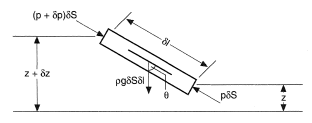
Consider a small liquid cylinder as shown in Figure 1. δS the cross sectional area is very small therefore there is no pressure variation across it. As there are no shear forces the only forces acting on it are those due to pressure on the surfaces and gravity. The only forces on the sides of the cylinder are normal to the sides and therefore have no component along the axis. Resolving forces along the cylinder axis yield:

If the difference in height between the ends of the cylinder δz = δl cos θ then the above equation simplifies to δp + ρgδz = 0. Taking the limit as δz → 0 gives:

In an incompressible liquid this equation can be integrated giving p + ρgz = constant. If a datum level of z is taken at a pressure of pa and the depth below this level is h, then the pressure p at this depth is:

This is the standard formula for pressure calculation in an incompressible liquid. Unless the variation of density with z is known, the pressure variation in a static compressible fluid cannot be found in the same way.
The three conditions for liquid equilibrium are therefore:
equal pressure over any horizontal plane;
density must be the same over any horizontal plane;
Eq. (1) must hold.
Thrust is exerted on every part of any surface in contact with a fluid. It is important to be able to resolve a resultant force over an area and the position of this force. For a horizontal plane, the position of the resultant force is at the plane's centroid; the resultant force is simply the pressure times the area. For planes at an angle, the following method can be used to determine the resultant force vector.

Figure 1. From Massey, B. S. (1968), Mechanics of Fluids, Van Nostrand Reinhold (International) Co., Ltd., London, with permission.

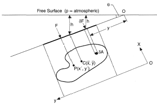
Figure 2. From Massey, B. S. (1968), Mechanics of Fluids, Van Nostrand Reinhold (International) Co., Ltd., London, with permission.
Consider the plane in Figure 2. Each element of area δA is subjected to a force due to the liquid:

p is the gauge pressure. Integrating over the whole area gives:

where  (i.e., the "first moment of area") is zero is known as the centroidal axis. The other centroidal axis is at
  , where this intersect is the "centroid" of area (
 ). The centroid of volume is obtained by integrating with respect to volume rather than area, i.e.,
  ,
,  .
.
This gives:

Therefore for an incompressible fluid,  is the pressure at the centroid. The total force exerted on the plane by the static fluid is the product of the area and the pressure at the centroid. The moment of the resulting force must equal the sum of the moments of the individual forces, therefore the line of action of F can be determined from the following equation:

Substituting F from Eq. (3) yields:

Similarly for x', taking moments about Oy:


The center of pressure (x',y') is always lower than the centroid of area except for horizontal surfaces. Curved surfaces require more complex mathematics but the resultant force vector can still be determined, see Streeter and Wylie (1983). Another method for determining the resultant force and line of action on a plane surface utilizes a "pressure prism" concept, see Streeter and Wylie (1983).
The resultant force acting on a body in a static fluid is called the "buoyant" or "buoyancy force", which always acts vertically upwards. It is the difference between the pressure forces exerted on its underside and upper side. This is equal to the gravity force of liquid that is displaced by the solid body, which forms Archimedes' principle. The centroid of buoyancy is therefore at the centroid of the displaced volume. All bodies floating in a static fluid have vertical stability as small vertical displacements set up restoring forces by increasing or decreasing the volume of fluid displaced.
Submerged bodies have rotational stability only if its center of gravity is below the center of buoyancy as shifts from equilibrium produce couples which return the body to equilibrium. If the center of buoyancy and gravity coincide the body is in neutral equilibrium. The stability of floating objects can be determined by considering Figure 3.
If a floating body with center of buoyancy Bo, and center of gravity G, is moved slightly away from its stable position (a) as shown in (b), the new centroid of buoyancy B' (which is the centroid of the displaced volume "abed") causes an upward thrust setting up a couple which restores stable equilibrium only if M, where the vertical through B' intersects the original center line, called the "met-center", is above G. If it is below, the body is unstable, and if G and M coincide, the body is in neutral stability. The distance MG is the "metacentric height".
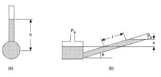
The measurement of pressure can be achieved by using suitable columns of liquids. Some simple manometers are shown in Figure 4.
The simple “piezometer tube" shown in Figure 4a gives the "gauge" pressure as p = ρgh. It cannot be used for negative gauge pressures as air would be sucked into the tube. "U-tube" manometers can be used to measure pressure differences, or gauge pressure if one of the two vertical arms is open to atmosphere. By using fluids of different density various pressure ranges can be measured. Utilizing two immiscible liquids in the arms, "micromanometers" can be constructed for the measurement of small pressure differences, see Streeter and Wylie (1983). A simpler method for measuring small pressure differences is the "inclined manometer" shown in Figure 4b. The inclination forces the liquid to travel a larger distance l in order to achieve the same increase in height x therefore:

If θ is small, there is considerable magnification of the meniscus' movement. For angles less than 5°, the position of the meniscus is difficult to determine.
For large pressure differences, U tube manometers can be connected in series, (see also Pressure Measurement).
REFERENCES
Massey, B. S. (1968) Mechanics of Fluids, Ch. 2, Sixth edn., Van Nostrand Reinhold (International) Co. Ltd, (1989).
Streeter, V. L. and Wylie, E. B. (1983) Fluid Mechanics, Ch. 2, First SI Metric edn. McGraw-Hill Book Co, 1986.
References
- Massey, B. S. (1968) Mechanics of Fluids, Ch. 2, Sixth edn., Van Nostrand Reinhold (International) Co. Ltd, (1989).
- Streeter, V. L. and Wylie, E. B. (1983) Fluid Mechanics, Ch. 2, First SI Metric edn. McGraw-Hill Book Co, 1986.

