The hydrocyclone is a simple piece of equipment that uses fluid pressure to generate centrifugal force and a flow pattern which can separate particles or droplets from a liquid medium. These particles or droplets must have a sufficiently different density relative to the medium in order to achieve separation.
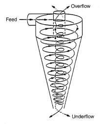
The flow pattern in a hydrocyclone is cyclonic. This is induced by tangential injection of the liquid into a cylindrical chamber, which causes the development of a vortex. The chamber has a restricted axial bottom outlet such that all of the liquid in the vortex can not escape via this outlet. Some of the liquid has to reverse its path and flow countercurrently to an axial top outlet. This reverse flow continues to rotate and an air core develops due to lower pressure at the axis of rotation.
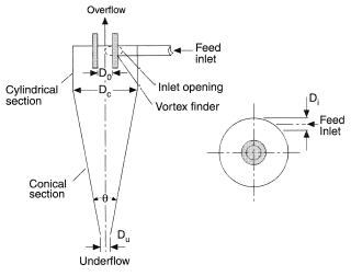
The conventional hydrocyclone consists of a cylindrical chamber connected to a conical body,which leads to the bottom outlet at the apex of the cone. This discharges the "underflow". The reverse flow is located by a pipe which projects axially into the top of the chamber, is termed the "vortex finder", and discharges the "overflow". The spiral flows and general shape of a hydrocyclone are illustrated in Figures 1 and 2.
The terms "bottom" and "top" in this context are used only to simplify the description. A hydrocyclone can work upside down or with an inclined or horizontal axis.
The fluid velocity patterns that develop are illustrated in Figures 3 and 4.
The existence of both downward and upward flow streams means that there is a locus of zero vertical velocity (Figure 3). At the same time both streams have a tangential velocity; that in the outer vortex decreases with increase in radius; that in the inner vortex decreases with decrease in radius. Velocities can be represented by the equation urn = constant, where n = – 1 in the inner vortex and can have values ranging from +0.5 to +0.8 in the outer vortex (see Vortex Flow).
This means that the outer fluid is approaching a free vortex and is experiencing shear whereas the inner fluid is rotating as if it were a solid body, i.e., with constant angular velocity. The peak tangential velocity is not necessarily at the position of zero vertical velocity.
These flow patterns and relationships have been established experimentally by Kelsall (1952) and Bradley (1965). They have been substantiated more recently by the application of Computational Fluid Dynamics, Pressdee (1989).
The size and shape of the vortex finder, the shape, of the chamber into which the feed liquid is injected and the geometry of the feed inlet all dictate the details of the flow pattern which will often include recirculatory streams (see Figure 5).
Due to this complexity many authors have produced correlations for both the separation efficiency and the pressure drop in hydrocyclones. Reviews have been published by Bradley (1965) and Svarovsky (1984).
The centrifugal force that is generated is capable of separating particulate solids down to around 5 to 10 microns in size. The smaller the diameter of the cyclone the higher the force and the higher the efficiency of separation of small particles. Long cone designs also exist which claim to give good efficiency with particles of less than 5 microns. A small diameter has, however, a low fluid capacity and in most cases such cyclones have to be manifolded and connected in parallel to be of industrial use.
Applications of the hydrocyclone were originally in the mineral processing industry for solid-liquid separation, i.e., the dewatering of particulate solids suspended in a water stream. The mechanism of separation is, however, dependent on both the difference in specific gravity of the particles and the liquid medium as well as the size of the particles (see Stokes' Law). This means that the hydrocyclone is also a classifier if the range of size of particles present in the feed stream is such that large will pass to the outer vortex and small will be entrained in the inner vortex (see Classifiers). The mineral processing industry uses hydrocyclones in this way. It also uses them as heavy media separators where the liquid density is increased to be intermediate between a light mineral and a heavy mineral. The light then passes to the overflow, the heavy to the underflow.
Applications extended to the chemical and food industries. In the main these are dewatering, for example, in concentrating a crystal slurry prior to centrifugation or in the concentration of starch suspensions.
In the latter case, use is also being made of the shear which exists in the outer vortex to strip gluten from starch particles.
Because of this shear it was originally believed that hydrocyclones would have limited application to the separation of liquid droplets. Development work primarily at Southampton University, Thew (1986) has, however, succeeded in disproving this. By elongating the cone and using narrow angles as small as 1° to 2° the shear zone is minimized relative to the non shear inner zone and finely dispersed oil in water can be separated down to a few tens of ppm. These special forms of hydrocyclone are now successfully marketed for removing oil from water in the refinery and offshore oil industries (see Liquid-Liquid Separation).
The hydrocyclone is now an established simple, practical tool widely used in all process industries.
REFERENCES
Bradley, D. (1965) The Hydrocyclone, Pergamon Press Limited, Oxford.
Bradley, D. and Pulling, D. J. (1959), Flow patterns in the hydraulic cyclone and their interpretation in terms of performance, Transactions Institution of Chemical Engineers, vol. 37, p. 34.
Kelsall, D. F. (1952), A study of the motion of solid particles in a hydraulic cyclone, Transactions Institution of Chemical Engineers, vol. 30, p. 87.
Pressdee, A. W. (1989) Process Industry Journal, p. 29, June.
Svarovsky, L. (1984) Hydrocyclones , Holt Rinehart and Winston.
Thew, M. T. (1986) The Chemical Engineer, All, p. 17, July-August.
References
- Bradley, D. (1965) The Hydrocyclone, Pergamon Press Limited, Oxford.
- Bradley, D. and Pulling, D. J. (1959), Flow patterns in the hydraulic cyclone and their interpretation in terms of performance, Transactions Institution of Chemical Engineers, vol. 37, p. 34.
- Kelsall, D. F. (1952), A study of the motion of solid particles in a hydraulic cyclone, Transactions Institution of Chemical Engineers, vol. 30, p. 87.
- Pressdee, A. W. (1989) Process Industry Journal, p. 29, June.
- Svarovsky, L. (1984) Hydrocyclones , Holt Rinehart and Winston.
- Thew, M. T. (1986) The Chemical Engineer, All, p. 17, July-August.


