The hot-wire anemometer, which is used to measure the instantaneous velocities of fluid flows, is based on the dependence of the sensor (gauge) heat transfer on the fluid velocity, temperature, and composition. A theoretical substantiation of this measurement method was set forth by King in his classic work in 1914. This method came into use for measuring turbulence characteristics following the development of a technique for compensation of the gauge's thermal lag.
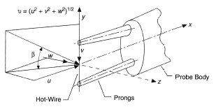
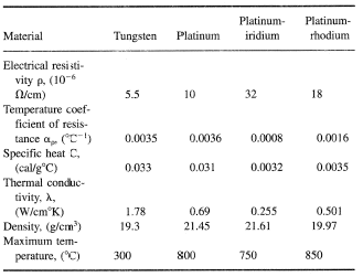
The sensor in the hot-wire anemometer is a thin metal wire (see Figure 1) or a film made of a material with a high temperature coefficient of resistance such as tungsten, platinum, platinum-rhodium, and platinum-iridium. The properties of materials used for manufacturing the sensors are presented in Table 1.
In these materials, resistance to a good accuracy depends linearly on temperature Rw = R0 (1 + αrgr;Tw), where R0 is the wire resistance at T = 0°C and Tw is the wire transfer (0°C).
Usually the gauge wire is between 1 to 10 μm in diameter D and from 0.5 to 2 mm in length 1. The wire is welded or soldered to stainless steel prongs with a diameter at the tips of 0.1 to 0.2 mm. In film gauges a 1 to 5 μm thick film is deposited on a cone-, wedge-, or cylinder-shaped substrate for measuring velocity or on a plane substrate for measuring shear stresses on the wall.
The gauge sensitivity to the flow velocity is provided by having the wire or film temperature Tw substantially higher than the flow temperature Tf, which is achieved by heating it by electric current. Measuring the velocity in gases is carried out with (Tw — Tf) typically in the range 180 to 200 K and in water, from 20 to 40 K. Measurement of voltage drop across the wire allows, if the physical properties of the gauge material and the mechanism of heat transfer are known, the determination of local fluid velocity. The hot-wire anemometer operates in two regimes, viz., a constant-current regime (Iw = const) when the gauge voltage pulsations are attributable to temperature variation and, hence, the wire resistance, and the regime of constant temperature (Tw = const), maintained by the feedback system with a variable current heating the sensor. One or the other regime is used depending on the specific character of measurements.
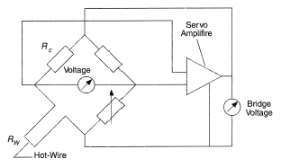
The gauge is connected by a shielded coaxial cable to one of the arms of Wheatstone bridge, the opposite arm being connected to a variable resistance controlling the overheat factor m = Rw/Rf (see Figure 2). In the constant- temperature hot-wire anemometer a feedback amplifier controls the bridge current so as not to upset the bridge balance and, consequently, to retain the gauge resistance and temperature constant and independent of the cooling rate. The instantaneous disbalance voltage of the bridge determines an instantaneous value of velocity pulsation. Contemporary instrument circuits afford, at an optimal alignment, a bandwidth up to 100 kHz.
The gauge thermal balance can be represented as

where QJ is the Joule heat  Rw, Qf.c the heat removed due to forced convection, Qfr.c and Qr heat losses due to free convection and radiation, Qh.cond heat removal to the sensor prongs, and Qh.cap the change of heat content of the sensor with temperature change owing to turbulent pulsations of velocity.
Repeated measurements have shown that at mean velocities U > 0.2 m/s, gauge temperature Tw < 1000 K and the length-to-diameter ratio 1/D > 200, the heat losses Qfr.c, Qr, and Qh.cond can be ignored, the more so if the gauge is individually calibrated. Qfr.c depends on the heat transfer coefficient α, the surface area A, the angle β subtended by the velocity vector direction and the normal to the sensor axis, and the temperature drop (Tw — Tf).
The heat transfer coefficient depends on the physical conditions of heat transfer on the surface and at 1/D > 200 and β = 0°C can be expressed in dimensionless from

where l is the length of the wire and D its diameter. When the effects of flow compressibility (Ma « 1) and rarefaction (Knudsen number Kn < 0.015) can be neglected, the dependence

is commonly used which describes heat transfer from cylinders for 0.7 ≤ Pr ≤ 103 and 10−2 ≤ Re ≤ 103. In Eq. (1), the fluid physical properties are taken at  = 0.5(Tw + Tf).
Alternatively, for gas flows, the heat transfer is well described by the relation

in which the constants have the following values:


The limiting number Re = 44 is determined by origination of a vortex trail in the cylinder wake. The indicated range of Re numbers makes it possible to measure the velocity by the gauge with D = 5 μm wire within the 0.2 ≤ U ≤ 550 m/s range.
The effect of compressibility is negligibly small at Ma < 0.3, but at high subsonic and supersonic velocities it must be allowed for. For supersonic velocities at 1.2 ≤ Ma ≤ 5 generalization of a vast body of experimental data yielded the expression

holding for Kn < 0.015. The influence of Knudsen number has to be allowed for in rarefied gases.
The heat transfer equations of hot-wire anemometer under consideration describe a general character of the functional dependence between the power put out by a sensor and the flow over it. In practice the specific gauge connected to a hot-wire anemometer electronic circuit is individually calibrated to determine the quantitative relation of the voltage at the bridge output E and the flow velocity U

where Rw is the resistance of the heated wire at Tw , Rc the resistance connected to the bridge in series with the gauge.
Calibration is carried out in the flow with known parameters (temperature, pressure) using a reliable velocity standard. It should be pointed out that individual calibration of the gauge takes account of the effects due to heat losses to the wire prongs.
As follows from Eq. (1), the constants A = 0.42πlλPr0.2 and B = 0.51lλ(D/ν)0.5Pr0.33 are determined by the geometrical parameters of the gauge and physical properties of the medium. For diatomic gases B does not depend on temperature and A is proportional to the coefficient of thermal conductivity λ, which is linearly dependent on T. In most practical cases n = 0.5 represents a good approximation as the power on Reynolds Number.
As a rule, in calibration and measurements the temperature difference (Tw – Tf) remains the same and if Tf = const in both cases, the above equation is simplified to

and the constants A1 and B1 are determined from the results of calibration by the least squares method.
The hot-wire anemometer gauge is very sensitive to contamination by dust, smoke, and oil vapor particles which may be present in the flow. As is shown in practice, the change of the gauge characteristic owing to contamination is proportional to the time of operation; therefore, it is advisable to calibrate the gauge prior to and after measurements and to filter thoroughly the air in the volume being investigated so that no particles larger than 0.2D in size are found in the flow.
If the flow approaches the sensor at an angle β, then the effective rate of wire cooling is determined by the relation

which has been verified experimentally at 1/D > 600.
The hot-wire anemometer, besides measuring a mean velocity, is an efficient instrument for diagnostics of turbulence characteristics, viz., intensities of temperature and velocity component fluctuations, coefficients of turbulent transfer of momentum and heat, spatial and temporal scales, etc.
Let U, V, and W be the relevant components of the velocity vector in the system of X, Y, Z coordinates (Figure 1) and their pulsation components be u, v, and w. The simplest case is represented by the vector of the averaged velocity, which lies in the XY plane, while V and W equal zero. If the wire is arranged in the XY plane at right angle to U, it will measure the axial velocity component. In this case the relation between the instantaneous values of voltage pulsations at the bridge output and the velocity pulsation is e = ∂E/∂U u = −Suu , where ∂E/∂U is the derivative of calibration dependence on the measured mean velocity U. Velocity pulsations in turbulent flow are random and their mean value is 0. Therefore, commonly the root-mean-square value of the velocity pulsations is measured

using root-mean-square voltmeters

Transverse velocity components are measured using gauges with tilted wires. If the wire tilted to the gauge axis at an angle of 45° is arranged in the UV plane, then the voltage at the bridge output will depend on two components of velocity pulsations, e1 = −Su1u −Sv2v . When the gauge is rotated through 180°, the wire will be inclined at an angle of 135° to the U direction and the signal will measure e2 = −Su2u + Sv1v . By using the results of measurements by perpendicular and tilted wires in two positions and solving the set of equations


the values of √ ,√
,√ , and
, and  are obtained.
An X-shaped gauge with two crossed strings is often used instead of a single rotated string. In this case a two-channel apparatus is needed for simultaneous measurement of two signals. If both strings have identical sensitivity coefficients, which is achieved by careful manufacturing of the gauge and by selecting appropriate wire overheating, the root-mean-square sum and difference of instantaneous values of signals from the wires  ,
,  determine intensities of pulsations of longitudinal and transverse velocity components, and
  , the component of turbulent stress
  . However, it should be pointed out that the requirements for identical characteristics of the wire are extremely high. If S1 = (1 + n)S2, then using this technique for measuring
  and
and  yields the error 100n%. An appropriate arrangement of gauge wires with respect to the mean velocity vector makes it possible to find
  and
and  ,
,  .
.
In nonisothermal flows the wire of hot-wire anemometer is simultaneously affected by temperature and velocity pulsations. Introducing the sensitivity coefficient Sθnn according to  we can write e = −SθU + Sθθ in the simplest case when the string is arranged perpendicular to the vector of the average velocity. Squaring and averaging yield

In order to determine  ,
,  , and
, and  , measurements are taken at several different values of (Tw — Tf) for realization of different correlations between the sensitivity coefficients Su and Sθ. The usual practice is to take 8 to 10 measurements of
  at various m = Rw/Rf and to treat the results by the least squares technique.
When measuring shear stresses on the wall τw the film gauge on the plane substrate is flush-mounted with the wall. The dependence between the power, put out by the film, and the shear stress τw is of the form

where Rf is the resistance of the hot film and the constants A and B are determined by precalibration in the flow given τw, e.g., stabilized isothermal flow in the pipe or in the boundary layer.
REFERENCES
Lomass, C. G. (1986) Fundamentals of Hot-Wire Anemometry, Cambridge Univ. Press.
Bradshaw, P. (1971) An Introduction to Turbulence and Its Measurement, Pergamon Press, Oxford.
References
- Lomass, C. G. (1986) Fundamentals of Hot-Wire Anemometry, Cambridge Univ. Press. DOI: 10.1002/zamm.19880680215
- Bradshaw, P. (1971) An Introduction to Turbulence and Its Measurement, Pergamon Press, Oxford. DOI: 10.1017/S0022112072281721


