Boilers of this type generate steam by extracting heat from hot fluid, generally a gas, which is produced as a by-product of a chemical reaction and has no intrinsic value as a chemical, or which is in the form of exhaust from a gas-turbine or internal combustion engine. Heat recovery boilers are also often found in association with high temperature processes such as steel and glass making.
It is not uncommon for these boilers to receive additional heat by supplementary firing of other by-products or by burning gas or light oil to raise the boiler inlet gas temperature to a level commensurate with the desired steam conditions.
The convective elements of boilers fired by municipal industrial or other waste materials are often referred to as heat recovery boilers although, apart from their geometry, they are more akin to the rear end of a furnace-fired boiler. Perhaps the most common heat recovery boiler is now the gas turbine heat recovery boiler.
Most heat recovery applications are characterized by low heat capacity fluids and low pressures, which combine to limit the velocities over the tubes and result in low heat transfer coefficients. For this reason, when the gases are clean, it is almost universal to use finning on the outside of the tubes. Most boilermakers use serrated helical finning but some utilize solid finning despite the reduced thermal efficiency and weight penalty involved. (See Augmentation of Heat Transfer.)
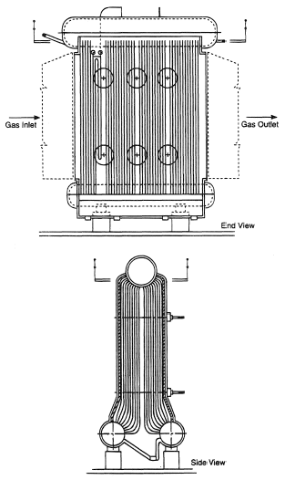
Boilers designed to recover heat from high temperature gases exhausted from glass making plant have to offer very low pressure drop to the gas stream and the tubes have to be arranged such that deposits, which are unavoidable as a result of the excess of sulfur trioxide in the gas, can be treated and removed regularly by soot-blowing. Such a boiler design is known as the tri-drum, illustrated in Figure 1. Economizer and superheater surfaces may be incorporated before and after the evaporator tubing as required to increase boiler efficiency or optimize steaming rate. A large capacity steam drum is provided to accommodate variations in the steam production rate throughout the soot blowing cycles.
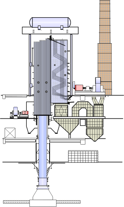
Boilers for recovering heat from steel-making plants are similar in concept to those above but, because of the wider swings in heat available from the source, these units are usually provided with auxiliary firing. A typical design is illustrated in Figure 2 in which the principal features are the elongated duct to draw the hot gases away from the converter, the water-cooled square-section furnace with auxiliary burners forming the up-pass and flue combined evaporator/economizer forming the parallel down-pass. Hoppers are provided to collect particulates carried over from the steel converter and the induced draft fan is used to draw hot gas through the heat recovery system. As in the preceding example, the large-capacity steam drum is noteworthy. Detailed layout of heating surfaces and choice of the balance between longitudinal and crossflow areas is a matter of optimization in conjunction with the auxiliary power of the fan.
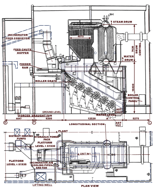
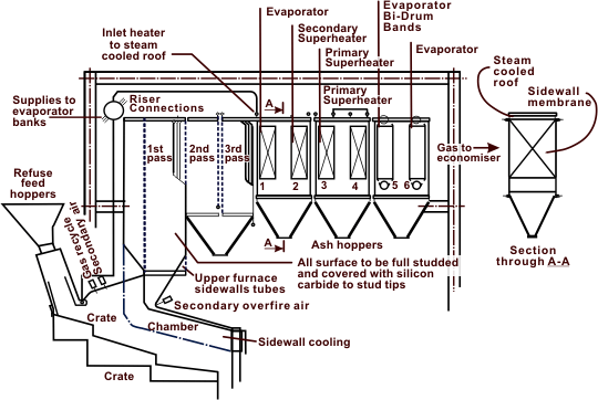
Boilers to recover the heat of combustion from waste incinerators may range from simple bi-drums such as shown in Figure 3 to combinations of these with banks of evaporator and superheater tubes mounted in water or steam-cooled ducts, the so called tail-end boiler as shown schematically in Figure 4.

Figure 1. Tri-drum heat recovery boiler for float-glass plant. Drawing reproduced by permission of Babcock Energy Ltd., UK.

Figure 2. Heat recovery boiler for steel works. (Reproduced courtesy of Austrian Energy & Environment-SGP/Waagner Biro.)

Figure 3. Bi-drum heat recovery boiler for waste heat incinerator. (Drawing reproduced by permission of Babcock Energy Ltd., UK.)

Figure 4. General arrangement of heat recovery boiler for MSW incinerator plant. (Drawing reproduced by permission of Babcock Ltd., UK.)
The principal considerations in design of these boilers are support and accommodation of relative expansion, ensuring adequate circulation under all operating conditions and provision of means of removing deposits from tubes. It is usual to support heat recovery boilers from the bottom but this leads to difficulties in matching the expansion of the furnace with that of the boiler, so top supported units offer simpler and often cheaper solutions. Ensuring adequate circulation involves providing separate supplies and risers for each section of the boiler that is subject to significantly different heat fluxes. Mechanical rapping gear is usually provided to ensure removal of deposits, which fall into hoppers mounted below each section of the boiler.