Bubble flow is defined as a Two-Phase Flow where small bubbles are dispersed or suspended as discrete substances in a liquid continuum. Typical features of this flow are moving and deformable interfaces of bubbles in time and space domains and complex interactions between the interfaces, and also between the bubbles and the liquid flow. According to the magnitude of these interactions, bubble flow is classified into four different flow regimes: i.e., ideally-separated bubble flow; interacting bubble flow; churn turbulent bubble flow; and clustered bubble flow, as shown in Figure 1.

In ideally-separated bubble flow, the bubbles do not interact with each other directly or indirectly. The bubbles thus behave like single bubbles. In interacting bubble flow, bubble number density becomes so large that the bubbles begin to interact with each other directly or indirectly due to collisions or the effects of wakes caused by other bubbles. With a further increase in bubble number density, the bubbles tend to coalesce to form so-called cap bubbles, and the flow changes to churn turbulent bubble flow. The flow contains cap bubbles formed in this way and also smaller bubbles; it is highly agitated due to the interactions between bubble motions and turbulent flow. The large bubbles occasionally form clustering of bubbles, as shown in Figure 1, and they behave like a single gas slug. After a certain travel, they sometimes coalesce to form a gas slug and sometimes, they separate into individual bubbles. This flow regime is thus a transition from bubble flow to slug or churn flow. Quantitative criteria for the transitions from ideally-separated to interacting bubble flow, and from interacting bubble flow to churn turbulent bubble flow are roughly 0.01 and 0.06 in void fraction, respectively. Detailed discussions of single bubble behavior are given by Wallis (1969).
Bubble flow is characterized by phase distribution phenomena, which exhibit different lateral void fraction profiles, depending on the volumetric flow rate of gas and liquid phases. Typical lateral void distribution patterns are given in Figure 2, representing wall void peaking, core void peaking and intermediate void peaking. For given flows of the two-phases in a given channel, the lateral void profile can take more or less any of these forms.
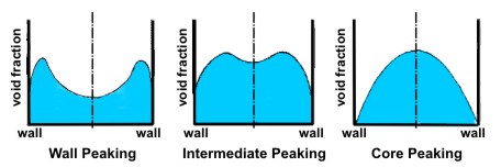
Figure 3 summarizes the trends of these void distribution patterns observed in vertically upward air-water flow in pipes using conventional types of bubble generators.
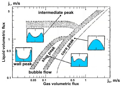
Figure 3. Lateral void distribution patterns map for air-water flow in vertical pipes obtained by Serizawa and Kataoka (1988).
Types of void peaking are due to a bubble segregation phenomenon which depends significantly on the size and shape of bubbles, as shown in Figure 4, obtained by Sekoguchi et al. (1974). The bubbles ranging form 2 to 5 mm in diameter tend to collect towards the wall. If the bubble size is carefully controlled under fixed flow conditions, the transition boundaries in Figure 3 shift towards lower or higher gas or liquid flow rate and therefore, existing flow pattern maps are no longer applicable.
The most important aspect of phase distribution phenomena is a close connection with turbulence and interfacial structures. This triangular link, as illustrated in Figure 5, strongly depends on the bubbles’ configurations; therefore, the bubble size and shapes are key parameters which determine the bubble flow characteristics such as turbulence (including wall shear stress) and interfacial structures (including interfacial shear stress) through different phase distribution profiles. Detailed discussions are given by Serizawa and Kataoka (1988).
Figure 6 represents some typical lateral phase distributions in air-water flows in channels. In horizontal flows, the buoyancy effected is predominant at low liquid flow rates. At higher liquid flows, the inertia effect overcomes the buoyancy effects and the profile thus becomes similar to vertical flows. The effects of physical properties of the fluids and turbulence fields are discussed by Serizawa and Kataoka (1988). The mechanisms of the phase distribution phenomena are supposed to be: 1) bubble segregation due to a lateral lift force acting on bubbles; 2) nonuniform pressure distribution induced by nonuniform turbulence field (Layey, 1988); 3) a force similar to diffusion force related to void fraction gradient; 4) bubble coalescence; and 5) effect of bubble trapment by eddies (Zun, 1986). The transverse lift force is usually expressed by

where CT is the transverse lift coefficient. For spherical bubbles immersed in an inviscid liquid, CT = 1/2. This coefficient is generally an experimentally determined constant. The lift force given by the above equation yields the force pushing the bubbles towards the wall for vertically-upward flow, and towards the tube center for vertically-downward flow. However, it does not always explain the trends shown in Figure 6. A vortex shedding model is discussed by Serizawa and Kataoka (1992).
A bubble diffusion model generally assumes under steady-state condition a balance of bubble flux due to diffusion (= DB ) with bubble migration due to lateral lift force. Based on a simple assumption of bubble-eddy collisions, the bubble dispersion coefficient DB is given by:

where dB and
 are Sauter Mean Diameter of bubbles for bubble size ranging 2 ~ 5 mm in diameter and turbulence, respectively. [See also Figure 7 cited by Serizawa and Kataoka (1992) from Hinata (1980)]. Other approaches are reviewed also by Serizawa and Kataoka (1992).
Bubble coalescence is another important phenomenon which we should consider in predicting flow development along a channel. Chesters and Hofman (1982) presented a criterion for this by considering the formation and thinning of a liquid film formed between the two bubbles with diameters dB1 and dB2. Here, urel is the relative velocity between the two deformed bubbles


The numerical prediction of phase distribution in bubble flow has progressed on the basis of the two-fluid model, in collaboration with turbulence models. Details should be referred to Lahey (1988)for the application of k − ε model and Lance and Lopez de Bertodano (1992) for Reynolds stress model. Several bubble diffusion modles have been also proposed (reviewed by Serizawa and Kataoka, 1992).
Typical 2D turbulence measurements upward air-water bubble flows in a vertical tube are demonstrated in Figure 8 (Serizawa and Kataoka, 1988). The numerical predictions of multidimensional turbulence can be made by a two-fluid model, coupled with an appropriate turbulence model. Typically, either two equation model like a κ − ε model and a τ − ε model based on Reynolds stress conservation equation are used for this purpose. (See Turbulence and Turbulence Modelling.) Detailed discussions are given by Lahey (1988), Lance and Lopez de Bertodano (1992), and Serizawa and Kataoka (1992). These models predict also the time-averaged liquid velocity and phase distributions. A linear superposition is often assumed for two-phase shear stress as follows (Sato et al., 1981):

where τB1, τS1 are the bubble-induced turbulence and the shear-induced turbulence, respectively. Other approaches are reviewed by Lance and Lopez de Berodano (1992).
Figure 8. 2-D turbulence measurements in vertical upward air-water flow (Serizawa and Kataoka, 1988).
The turbulence modification in bubble flow is either to increase or to decrease local turbulence depending on the flow conditions, as shown in Figure 8. A criterion for turbulence reduction or promotion is constructed for air-water flows in Figure 9 in terms of the liquid flux jL versus gas flux jG.
Figure 10 is a generalized expression for turbulence modification proposed by Gore and Crowe (1989) for dispersed flows. The coordinate is a nondimensional particle or bubble size where the integral scale of turbulence le is chosen as the characteristic scale. The turbulence reduction occurs for dp/le (or dB/le) ≤ 0.1.
Local turbulence energy production, dissipation and diffusion rates are important quantities in turbulence reduction/enhancement. Relative motions between the bubbles and the liquid flow produce both additional turbulence and dissipation due to viscous effect, depending on the scale of interfaces and turbulence eddies. Discussions are given and reviewed by Serizawa and Kataoka (1992). However, generally accepted physical explanations for the mechanisms have not yet been developed, although turbulence modification may be predicted to some extent by numerical methods (Lahey, 1988; Lance and Lopez de Bertodano, 1992).
Turbulence scales, mixing length and turbulence energy spectra are reported by Michiyoshi and Serizawa (1986) and are reviewed by Serizawa and Kataoka (1988, 1992).
The interfacial area density (or concentration) is defined as the sum of the interfaces per unit volume of two-phase mixture. This term appears in basic conservation equations in two-fluid model formulations. In order to close the equation system, this term is usually given as a closure law. With an assumption of spherical bubbles, the local interfacial area concentration αi is given as:

Experimental results modify the above equation. Detailed discussions are given by Serizawa and Kataoka (1992). Interfacial transfer terms appearing in two-fluid model, are discussed by Lahey and Moody (1975).
Multidimensional bubble flow characteristics with phase change are less known than adiabatic bubble flows. Particularly, the structure and temperature field in near heated wall region is poorly understood. In one-dimensional calculation of void fraction distribution along flow direction, the Saha and Zuber correlation is useful to predict the point of net vapor generation.
Thermally-controlled region Pe (= GDecpL/λL) ≤ 70,000:

Hydrodynamically-controlled region Pe > 70,000:

The calculation methods to predict axial void distributions are given by Lahey and Moody (1975). Several interfacial transfer terms are referred also to this.
According to homogeneous flow model, the viscosity of bubbly mixture is given by either of the following equations:

For small bubbles with diameters less than 1 mm suspended in a liquid, the mixture viscosity is given by the Einstein equation:

For emulsion, the Taylor equation can be used:

Electrical conductivity is estimated by the following equations:

REFERENCES
Chesters, A. K. and Hofman, G. (1982) Bubble Coalescence in Pure Liquids: Mechanics and Physics of Bubbles in Liquids (Ed. L. van Wijingaarden). Matinus Nijhoff Publishers, pp. 353–361.
Gore, R. A. and Crowe, C. T. (1989) Effect of Particle Size on Modulating Turbulent Intensity, Int. J. Multiphase Flow, 15:279–285. DOI: 10.1016/0301-9322(89)90076-1
Lahey, R. T. Jr. and Moody, F. J. (1975) The Thermal-Hydraulics of a Boiling Water Nuclear Reactor. ANS Monograph.
Lahey, R. T. Jr. (1988) Turbulence and Phase Distribution Phenomena in Two-Phase Flow: Transient Phenomena in Multiphase Flow (Ed. N. H. Afgan). Hemisphere Publishing corporation, pp. 139–177.
Lance, M. and Lopez de Bertodano, M. (1992) Phase Distribution Phenomena and Wall Effects in Bubbly Two-Phase Flows, Proc. of the 3rd Int. Workshop on Two-Phase Flow Fundamentals, June 15–19, 1992, London, UK.
Michiyoshi, I. and Serizawa, A. (1986) Turbulence in Two-Phase Bubbly Flow, Nucl. Eng. and Design, 95:253–267. DOI: 10.1016/0029-5493(86)90052-X
Sato, M., Sadatomi, M., and Sekoguchi, K. (1981) Momentum and Heat Transfer in Two-Phase Bubbly Flow-I, Int. J. Multiphase Flow, Vol. 7. DOI: 10.1016/0301-9322(81)90003-3
Sekoguchi, K., Sato, Y., and Honda, T. (1974) Two-Phase Bubble Flow (First Report), Trans. Japan Soc. Mech. Engrs. 40:1395–1403.
Serizawa, A. and Kataoka, I. (1988) Phase Distribution in Two-Phase Flow: Transient Phenomena in Multiphase Flow (Ed. N. H. Afgan). Hemisphere Publishing Corporation, pp. 179–224.
Serizawa, A. and Kataoka, I. (1992). Dispersed Flow, Proc. of the 3rd Int. Workshop on Two-Phase Flow Fundamentals, June 15–19, 1992, London, UK.
Wallis, G. B. (1969) One-Dimensional Two-Phase Flow. McGraw Hill, N.Y.
Zun, I. (1986) Influence of Void Fraction on the Pressure Drop Prediction in Bubbly Flow, Proc. of the 5th Chemical Engineering Congress, Toronto, pp. 155–162.
References
- Chesters, A. K. and Hofman, G. (1982) Bubble Coalescence in Pure Liquids: Mechanics and Physics of Bubbles in Liquids (Ed. L. van Wijingaarden). Matinus Nijhoff Publishers, pp. 353–361. DOI: 10.1007/BF00385965
- Gore, R. A. and Crowe, C. T. (1989) Effect of Particle Size on Modulating Turbulent Intensity, Int. J. Multiphase Flow, 15:279–285. DOI: 10.1016/0301-9322(89)90076-1
- Lahey, R. T. Jr. and Moody, F. J. (1975) The Thermal-Hydraulics of a Boiling Water Nuclear Reactor. ANS Monograph.
- Lahey, R. T. Jr. (1988) Turbulence and Phase Distribution Phenomena in Two-Phase Flow: Transient Phenomena in Multiphase Flow (Ed. N. H. Afgan). Hemisphere Publishing corporation, pp. 139–177.
- Lance, M. and Lopez de Bertodano, M. (1992) Phase Distribution Phenomena and Wall Effects in Bubbly Two-Phase Flows, Proc. of the 3rd Int. Workshop on Two-Phase Flow Fundamentals, June 15–19, 1992, London, UK.
- Michiyoshi, I. and Serizawa, A. (1986) Turbulence in Two-Phase Bubbly Flow, Nucl. Eng. and Design, 95:253–267. DOI: 10.1016/0029-5493(86)90052-X
- Sato, M., Sadatomi, M., and Sekoguchi, K. (1981) Momentum and Heat Transfer in Two-Phase Bubbly Flow-I, Int. J. Multiphase Flow, Vol. 7. DOI: 10.1016/0301-9322(81)90003-3
- Sekoguchi, K., Sato, Y., and Honda, T. (1974) Two-Phase Bubble Flow (First Report), Trans. Japan Soc. Mech. Engrs. 40:1395–1403.
- Serizawa, A. and Kataoka, I. (1988) Phase Distribution in Two-Phase Flow: Transient Phenomena in Multiphase Flow (Ed. N. H. Afgan). Hemisphere Publishing Corporation, pp. 179–224.
- Serizawa, A. and Kataoka, I. (1992). Dispersed Flow, Proc. of the 3rd Int. Workshop on Two-Phase Flow Fundamentals, June 15–19, 1992, London, UK.
- Wallis, G. B. (1969) One-Dimensional Two-Phase Flow. McGraw Hill, N.Y.
- Zun, I. (1986) Influence of Void Fraction on the Pressure Drop Prediction in Bubbly Flow, Proc. of the 5th Chemical Engineering Congress, Toronto, pp. 155–162.