Double-pipe exchangers is the generic term covering a range of jacketed 'U' tube exchangers normally operating in countercurrent flow of two types:
True Double Pipes: Single inner pipe formed into a removable 'U' or element, with either longitudinal fins or centralizing supports. Typical standard sizes, layout and overall dimensions are shown in Figure 1 and finned geometric data are in Table 1.
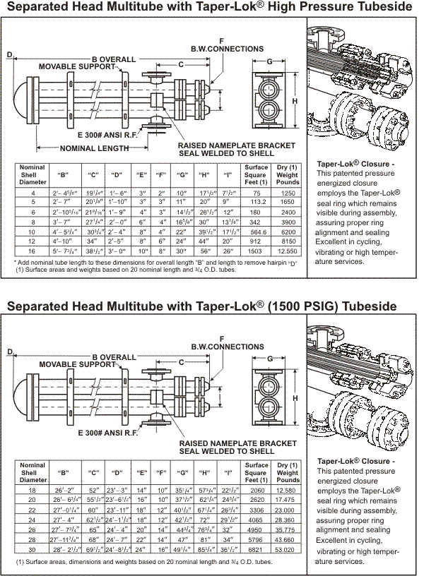
Multitubular Hairpins: A removable bundle of U-tubes with either shell-&-tube type segmental baffles, rod type supports or longitudinal fins. A typical layout is shown in Figure 2, which shows longitudinal fins. These units are available as standard designs ranging from 75mm (3" N/B) to 406 mm (16" N/B) pipe sizes. Larger units up to 762 mm (30" N/B) are also available from some manufacturers (e.g., Brown Fintube). The larger units comply fully with TEMA-1988 and standard industry shell-&-tube specifications. Typical dimensions are shown in Figure 3. (See Figure 3 on page 326.) Geometric data are given in Table 2, based on the use of 19.7 mm (3/4") OD tubes arranged on 23.8125 mm (15/16") triangular pitch.
Unlike TEMA-type BEU units, the bundle or element is removed from the U-tube end of the exchanger, which means the tube sheets have to slide through the shells. Special closures are required with a combination of split flanges, split rings and sealing rings as shown in Figure 2.
The shells are supported in bracket assemblies designed to cradle both shells simultaneously. The brackets are configured to permit the modular assembly of many hairpin sections into an exchanger bank for inexpensive future expansion. This construction also allows the shells to be fully supported without welding the brackets to the shells, minimizing the transfer of thermal stresses to the pipework.
The multitubular hairpin units should be more economic than TEMA-type shell-&-tube units when one or more of the following criteria apply:
Temperature cross or very close temperature approach. Often one counter-current hairpin unit will replace two multipass shell-&-tube units in series.
High tube-side design pressure (>5,000 kPa). The smaller diameter compact hairpin unit will have thinner flanges & closures, hence a lower cost. Present mechanical design technology has allowed the production of dependable, removable bundle hairpin multitubular units at tube-side design pressures of up to 82,500 kPa.
Alloy tubeside materials. Same as (2), hence a lower cost.
Where heat transfer augmentation is the best solution. Hairpin exchangers are normally single-pass so tube-side heat transfer enhancement devices, such as twisted tape turbulators, cores, cored helixes and helixes, are used to increase the velocity and/or film coefficient. A recent development at Brown Fintube has improved the design of units with horizontal tube-side boiling and dry exit vapor. Shell-side longitudinal fins can be beneficial when the tube-side film coefficient is significantly higher (>2 times) than the shell-side.
Where differential expansion is a problem. Multitubular hairpin units can be used as alternatives to TEMA floating-head types because the minimum U-bend dimension is much larger than a TEMA-type BEU unit, such that flexible mechanical tube cleaning devices can be used.
Thermal design is normally carried out by the manufacturer, but you can use shell-and-tube exchanger programs by specifying a single-pass BEM unit with twice the nominal hairpin length.
The tube-side method is identical to a one-pass BEM unit.
The shell-side is also identical when using segmental baffles. Rod-type baffles are often used with triangular pitch, so the shell-and-tube 'Phillips rod-baffles' method cannot be used as this is only for square pitch. True longitudinal flow can be simulated with triangular pitch by specifying triple segmental baffles on maximum pitch. If longitudinal fins are used, a tube-side type correlation is applied with an equivalent diameter in place of the tube outside diameter. Also, the finned area is not as effective as bare tube area so a fin efficiency must be used. It is possible to carry out such calculations by hand and the method is adequately covered in various textbooks, including Process Heat Transfer [Hewitt et al. (1994)].
The HTFS shell-&-tube program TASC will have a multitubular hairpin and double-pipe option installed by 1996.
REFERENCES
Brown Fintube UK, PO Box 790. Wimborne, Dorset, BH21 5YA, UK.
Brown Fintube Company, 12602 FM 529, Box 40082, Houston, Texas 77240, USA
TEMA (1988) Standards of Tubular Exchanger Manufacturers Association, 7th ed., New York.
Hewitt, G. F, Shires, G. L., and Bott, T. R. (1994) Process Heat Transfer, CRC Press, Boca Raton, FL.
HTFS: Heat Transfer and Fluid Flow Service. 392.7 Harwell, Didcot, Oxfordshire, OX11 ORA, UK.
References
- Brown Fintube UK, PO Box 790. Wimborne, Dorset, BH21 5YA, UK.
- Brown Fintube Company, 12602 FM 529, Box 40082, Houston, Texas 77240, USA
- TEMA (1988) Standards of Tubular Exchanger Manufacturers Association, 7th ed., New York.
- Hewitt, G. F, Shires, G. L., and Bott, T. R. (1994) Process Heat Transfer, CRC Press, Boca Raton, FL.
- HTFS: Heat Transfer and Fluid Flow Service. 392.7 Harwell, Didcot, Oxfordshire, OX11 ORA, UK.


