The operation of a differential pressure flow meter device depends on measurement of the pressure differential caused by an arrangement installed in a pipeline, or by elements of the pipeline. A flow meter consists of a primary converter which builds up differential pressure, a differential manometer and the connecting pipes between them.
Flow meters in the form of contraction devices (see Orifice Flow Meter) are the most common. Here, differential pressure is created by converting part of the potential energy of the flow into kinetic energy by changing the cross-section of the pipeline. The difference (Δp) between the pressure upstream of the contraction device (pin) and the pressure downstream of the device (pout) is related to the flow rate
 by
by
 , where S is the cross sectional area of the channel upstream of the meter and α is a characteristic coefficient.
The second group of flow meters depends on the differential pressure caused by a local hydraulic resistance in the pipeline. The flow condition of such a resistance is usually laminar in order to obtain a linear dependence
 . Such a dependence exists if the length of the capillary tube bank (Figure 1a) or of flat thin orifices is l = (200 - 300)d, whereas d is the hydraulic diameter. Such converters are usually used in measuring very small flow rates. As an alternative to capillary tubes, primary converters may be used in which the resistance is produced by a porous septum (Figure 1b). A linear dependence
 is realized in this case for l ≤ 0.25 mm.
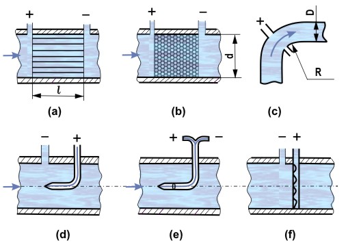
The operation of centrifugal flow meters (elbow meters) is based on the fact that in curvilinear sections of the pipeline (knees), differential pressure occurs due to the effect of a centrifugal force which in turn, depends on the flow rate (Figure 1c). For a pipeline with diameter D and with a knee having a radius of curvature R, the flow rate is determined by the relation
 0.5. As a large body of experiments show, α = 1 ± 0.04 for Re > 2 × 10⁵. The accuracy of measurement of R and D must not be less than ±0.5% and ±0.15%, respectively. Pressure taps are located on the diameter which coincides with the bisector of the central angle of knee turn and must be strictly perpendicular to the inner surface of the pipe. A straight section not less than 25D long must be placed ahead of the knee. The main advantage of such flow meters is the absence of any obstructions in the flow. They are mainly used for measuring water flow rate.
Flow meters with pressure devices, which include the Pitot tube (Figure 1d) and Prandtl tube (Figure 1e) and a device which averages the impact pressure along the flow section (Figure 1f), measure the impact pressure which is the sum of the dynamic, pd = 0.5ρu2, and static, ps, pressures. The static pressure is measured either on the pipeline wall, or with the help of a static-pressure tube, or with Prandtl's tube (Figure 2). The differential manometer measures Δp = pd − ps, and the velocity at the point of probe location is defined from the relationship u = k(2ΔP/ρ)0.5. The main design dimensions of the Prandtl pipe are given in Figure 2a For such a pipe, k = 1 ± 0.0025. It consists of two concentric pipes: the central one has an open-end facing into the flow and takes up the impact pressure; on the outer pipe, a static pressure connection in the form of 6-8 holes measuring 0.1-0.2 d in diameter is located at a distance of 6 d from the probe nose. The area of the probe midsection must not exceed 2% of the flow section of the pipeline. With tubes measuring impact pressure, a local velocity is measured; to obtain the value of the flow rate, various methods are used: the method of integration of the velocity profile; the measurement of average velocity ū at the point of the velocity profile where the local velocity is equal to the average velocity (in a developed turbulent flow in a smooth round pipe, the value of ū is obtained at a distance of 0.768R from pipe center); measurement of the velocity on the pipe axis u0 coupled with the use of the relation between ū and u0 for a developed turbulent flow in hydraulically-smooth round pipes the ratio (ū/u0 is a function of Re as shown in Table 1).

Table 1. Ratio of mean velocity (ū) to axial velocity (u0) for fully developed turbulent flow in a smooth pipe
| Re | 4×10³ | 104 | 5·104 | 105 | 5·105 | 106 |
| ū/u0 | 0.791 | 0.800 | 0.812 | 0.817 | 0.837 | 0.846 |
All these measurements call for a sufficiently-long, straight section of the pipeline 1 = (25 — 40) D ahead of the place of measurement.
In pressure averagers (Figure 2b), an averaged over-the-pipe-line radius value of dynamic head is measured rather than the local value. The primary converter consists of a pipe located along the pipeline diameter, which has a number of holes facing the flow. The outer diameter of the probe d should be within the limits of d = (0.02 - 0.05) D, the wall thickness δ ≤ 0.1 d, and the diameter of the exhaust holes of impact pressure tap dexh = (2 - 3) δ. There is a central tube which has tappings (normal to the flow direction) located at a distance of 0.95R from the pipe axis; this allows measurement of the average impact pressure. For D ≥ 50 mm, Re ≥ 2 × 10⁵ and a long enough straight section of the pipeline ahead of the measuring section, the pipe coefficient k = 1. With the help of such a pipe, ū is measured and the flow rate is derived from the equation

The static pressure on the wall of the pipeline is tapped at a distance of 2d upstream of the pressure averager pipe.
REFERENCES
Fluid Meters. Their Theory and Application. (1971) Report of ASME, Research Committee on Fluid Meters, New York, Published by ASME.
References
- Fluid Meters. Their Theory and Application. (1971) Report of ASME, Research Committee on Fluid Meters, New York, Published by ASME.