Whereas in recuperators, where heat is transferred directly and immediately through a partition wall of some kind, from a hot to a cold fluid, both of which flow simultaneously through the exchanger, the operation of the regenerative heat exchanger involves the temporary storage of the heat transferred in a packing which possesses the necessary thermal capacity. One consequence of this is that in regenerative heat exchangers or thermal regenerators, the hot and cold fluids pass through the same channels in the packing, alternately, both fluids washing the same surface area. In recuperators, the hot and cold fluids pass simultaneously through different but adjacent channels.
In thermal regenerator operation the hot fluid passes through the channels of the packing for a length of time called the "hot period," at the end of which, the hot fluid is switched off. A reversal now takes place when the cold fluid is admitted into the channels of the packing, initially driving out any hot fluid still resident in these channels, thereby purging the regenerator. The cold fluid then flows through the regenerator for a length of time called the "cold period," at the end of which the cold fluid is switched off and another reversal occurs in which, this time, the hot fluid purges the channels of the packing of any remaining cold fluid. A fresh hot period then begins.
During the hot period, heat is transferred from the hot fluid and is stored in the packing of the regenerator. In the subsequent cold period, this heat is regenerated and is transferred to the cold fluid passing through the exchanger.
A cycle of operation consists of a hot followed by a cold period of operation together with the necessary reversals. After many cycles of identical operation, the temperature performance of the thermal regenerator in one cycle is identical to that in the next. When this condition is realized, the heat exchanger is said to have reached "cyclic equilibrium" or "periodic steady state." Should a step change be introduced in one or more of the operating parameters, in particular, the flow rate and entrance temperature of the fluid for either period of operation, or the duration of the hot and cold periods, the regenerator undergoes a number of transient cycles until the new cyclic equilibrium is reached.
In the most common counterflow or contraflow regenerator operation, the hot gas passes through the regenerator in the opposite direction of the cold fluid. In less efficient parallel flow or co-flow the hot and cold fluids pass through the channels of the packing in the same direction(†). (†) In theory, it is possible to imagine a cross-flow regenerator in which the hot and cold fluids flow in directions perpendicular to one another. This is rarely, if ever, realized in practice although cross-flow recuperators are common.
The periodic operation of regenerators can exploit the periodic operation of the system to which the exchanger is attached. For example, in hot climates, day time heat can be stored in a packing by passing the warm atmospheric air through it: this heat can then be recovered by blowing cold night time air through the same packing during the evening to provide at least some supplementary warming of the living space in a building. Hausen (1976) suggests that the throat and nasal passages act as a regenerator packing in cold weather. When an animal breathes in cold air, it is warmed as it passes through the nose and throat before the air reaches the lungs, thereby protecting the lungs from the effects of cold temperatures. As the animal breathes out, the same passages in the nose and throat are warmed by the air leaving the lungs. Clearly, the temperature of the throat and nasal tissue is also regulated by the flow of blood through it.
In general, however, a continuous supply of heated fluid is required so that the discontinuous operation of the regenerator, which is inherent in its design, must be concealed in some way.
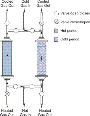
The most obvious technique for realizing "apparent" continuous operation, is to use two or more regenerators operating out of phase with respect to one another so that while one regenerator is supplying heated fluid, the other regenerator(s) is storing heat from the heating fluid. An apparently easy way to do this is by enclosing the set of regenerators within a system of ducts or pipes fitted with valves to facilitate the switching of the regenerators at the end of a period of operation. As one set of valves close, at a reversal, so another set open: the flow of hot gas, for example, is diverted from one regenerator to the other by the closing of such a set of valves and the opening of the other. Simultaneously, the flow of cold gas is switched from the other regenerator in a symmetric fashion. (See Figure 1.) Such an arrangement is called a system of fixed bed regenerators, in contrast to the rotary regenerator which will be described shortly.
The reversal process can be more complicated than this. The following are important considerations.
Some applications require that the regenerator(s) be purged before the supply of heated fluid, for example, is switched from one regenerator to the next. In this case, the cold period of one regenerator is extended to maintain the supply of heated fluid to the external process to which the set of regenerators is attached. Meanwhile, the hot period of the other regenerator is terminated and that regenerator is completely purged before its cold period begins. This regenerator then shoulders the burden of supplying heated fluid from the other regenerator whose end of cold period reversal can begin. Such arrangements necessarily complicate the valve and duct facilities associated with the set of regenerators: in addition, a suitable exhaust for fluids purged from the regenerator, not permitted to enter the heated fluid stream, for example, must be provided.
Where the fluids are gases, it is not uncommon for the pressure of the cold gas stream, for example, to be significantly higher than that of the hot gas strewn. In this case, at the end of a cold period, time must be allowed during the reversal for the regenerator to be decompressed before the hot period is permitted to begin. Similarly, time must be allowed at the start of a "cold" period for the pressure of the cold gas in the regenerator to build up before the cold period proper can begin. Again, additional valves and pipework must be provided to accommodate these complications.
In high temperature regenerators, it is desirable not to have any valves at all at the hot end of the regenerators. Where this cannot be avoided, the valves are often very expensive, perhaps requiring to be water cooled to avoid malfunction at high temperatures. It is often the case, however, the hot end of the regenerator is attached to the furnace or boiler to where pre-heated air, for the combustion of a fuel gas, is supplied directly, and from where, after a reversal, the hot gas, frequently the waste products of combustion of the fuel, is extracted directly to the regenerator. In this way, no valves are required between the regenerator and the furnace or boiler. The necessary suction of the hot gas through the regenerator is achieved by attaching the exit duct for this gas at the cold end of the regenerator to a chimney, which, if tall enough, will provide the necessary updraft. Valves are employed safely at the cold end of the regenerator to switch the heat exchanger from the chimney exhaust for waste gases to the supply of cold air for the cold period of regenerator operation, or vice-versa. A continuous supply of preheated combustion air is achieved by attaching several regenerators to a furnace or boiler, operating as necessary, out of phase with respect to one another.
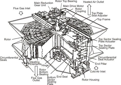
In the Ljungström air preheater, or rotary regenerator, the porous packing is rotated around an axis. In its simplest form, the packing is divided into two gas tight sections and the hot and cold gases flow simultaneously in a direction parallel to this axis, usually in contra-flow, through these different segments of the packing. As the packing rotates through the hot gas stream, it stores heat, as in the hot period of a fixed bed regenerator. This thermal energy is literally transported into the cold gas stream as the packing is rotated. Once in the other gas stream, the heat is regenerated and is passed to the cold gas, as in the cold period of operation of a fixed bed system.
It is impossible to secure completely gas-tight seals at the junctions between the ducts, carrying the hot and cold fluids, respectively, and the moving surfaces of the rotating heat storing mass of the regenerator packing. However, if it is required to prevent preheated air, for example, from being contaminated by the waste combustion products which supply the necessary thermal energy, it is arranged that the pressure of the air is deliberately higher with the consequence that any leakage under the seals of the rotary regenerator is of air into the stream of hot combustion products.
When the rotor first passes from the hot gas to the cold gas stream, for example, a body of hot gas in the voids of the regenerator packing, is carried by rotation into the cold gas stream and must be purged from the regenerator, as in the fixed bed mode of operation. In some applications, it is vital that this carryover gas should not be permitted to contaminate the stream of cold gas being heated by the exchanger. In these circumstances, an additional sector is provided in the packing so that gases purged from the regenerator at the end of the hot period, for example, can be sent off to a separate exhaust, possibly fed back into the hot gas stream.
Another version of the rotary regenerator exists in which the packing remains stationary but the hoods at both ends of the packing, through which the hot and cold fluids pass in separate ducts, rotate instead.
The relationship between the heat transferred between the fluid and the solid packing, and the heat absorbed by that packing is given by the equation
On the other hand, the relationship between the thermal energy transferred between the solid packing and the fluid, and the heat taken up by the fluid passing through the regenerator is given by the equation
These equations apply equally to the hot and cold periods of regenerator operation, for which the relevant parameters may be different. We therefore denote the bulk heat transfer coefficient in the hot period by  , in the cold period by
  , for example.
The boundary equations relate first to the entrance gas temperature, Tf,in, where it is assumed that Tf,in(t) = constant in each period of operation. Next, we specify that Equations (1) and (2) consider the gas to be moving from y = 0 to y = L in both the hot and the cold periods of regenerator operation. In order to specify that the solid temperature distribution at the start of a period is equal to that at the end of the previous period, and to incorporate the contraflow operation of the regenerator, the boundary conditions are written in the form


where P is the duration of the hot period and P' the duration of the cold period.
The most important assumption embodied in this model is that the resistance to heat transfer at the surface of the solid and the resistance due to the finite conductivity of the packing, in a direction normal to fluid flow, can be incorporated together in a "bulk" or "lumped" heat transfer coefficient α where, using a development of [Hausen Hausen (1942)] the defining equation is given by

where δ is the thickness of the packing and λδ its thermal conductivity.
The function Φ attempts to reproduce the effect of the very rapid temperature changes within the packing, immediately after a reversal, at the start of a hot or cold period. It is a function of the dimensionless parameters Ω and Ω' , where

In the case where the packing can be considered to be a simple, plain wall of thickness δ

for

where

then

Similar expressions are available for the case where the packing can be regarded as a collection of solid cylinders or as a bed of spheres. Reference should be made to the later work of Hausen [(Hausen (1976)]. The case for hollow cylinders is covered in the paper by Razelos [Razelos (1967) et al.].
It is also assumed in this model that the thermal conductivity in a direction parallel to fluid flow, so called "longitudinal conductivity", can be neglected. This problem is discussed in the paper by Bahnke and Howard [Bahnke and Howard (1964)]. It is further idealized that the flow of fluid is uniform through the cross-section of the packing in both periods of operation. It is generally allowed, however, that the relevant thermophysical properties of both fluid and solid, including the heat transfer coefficients, can vary spatially and timewise, as a function of temperature. Equally, it is permitted to consider the case where the mass flow rates of the fluids in either or both periods of regenerator operation can vary with time.
The model is greatly simplified in the so called "linear model" in which it is further assumed that the relevant thermophysical properties of both fluid and solid, including the heat transfer coefficients, do not vary spatially and timewise, but are constant. On the other hand, they are permitted to be different between the hot and cold periods. Similarly, it is assumed that the gas flow rates are constant, although, in general  . In these simplifying circumstances, it is possible to reduce Equations (1) and (2) into the forms
Here, the dimensionless parameters, η for time and ξ for length, are introduced where

Upon setting t = P and y = L, each period of regenerator operation is defined in terms of two dimensionless parameters given the names by Hausen [Hausen (1929)] "reduced period", Π, and "reduced length," Λ. Equations (14) below define these for hot period operation:
For the cold period, the corresponding equations are

In this linear model, it is also possible to treat the hot period inlet temperature Tf,in = 1.0 and the "cold" period inlet temperature Tf,in = 0.0 (†).
† This is equivalent to setting

where τf and τs are the "real" fluid and solid temperatures and Tf and Ts are the corresponding dimensionless temperatures.
It is not within the orbit of this text to describe the many and varied methods of solution of these differential equations which have been developed over several years. Be it sufficient to say that there are two classes of method of solution, the "open" methods and the "closed" methods. In the open methods, a starting distribution of temperature, Ts(ξ,0), of the solid at the start of a hot period is assumed. The model of the regenerator is then cycled through many cycles by solving Equations (11) and (12), for example, through successive hot and cold periods of operation. This simulation of the heat exchanger is then permitted to run until the periodic steady state is realized. In the closed methods, it is simply assumed that the solid temperature distribution Ts(ξ,0)(n), at the start of the nth cycle is equal to that, Ts(ξ,0)(n+1), at the start of the following cycle, at cyclic equilibrium. The equations are then solved, often in integral equation form, as a boundary-value problem. No transient cycles prior to equilibrium be established are simulated. It turns out that closed methods are useful for solving a range of linear problems but that they become extremely complicated when dealing with nonlinear problems, that is when it is permitted that the relevant thermophysical properties of both fluid and solid, including the heat transfer coefficients, can vary spatially and timewise, as a function of temperature and/or when the mass flow rates of the fluids in either or both periods of regenerator operation can vary with time. In these cases, the open methods are more easily adopted
The packing of a regenerator varies considerably from one type of application to another. On the one hand, the selection of the heat storing mass is determined by the harsh, or otherwise, operating conditions under which the regenerator is required to operate. On the other, the possible operating arrangements with such packings is best understood in the context of the dimensionless parameters Λ and Π. For a given reduced length, Λ, the maximum thermal performance, it can be shown, is achieved by employing as small a value of reduced period, Π as possible.
The ratios

represent the heat capacity of the packing per hot period and per cold period respectively. The effective interface between the fluid flowing through the regenerator at any instant and the heat storing packing are the products  and
and  for the hot and cold periods. The larger these interfaces, the greater must be the heat capacity per period to accommodate the thermal energy involved.
In other words, the ratios

must be matched by periods which yield small enough values of Π and Π' so that as good a thermal performance of the regenerator as possible can be obtained.
This can be considered in another manner: economies in regenerator size can be obtained if thin packings are used where the area to mass ratio, A/M for the hot period, A'/M' for the cold period, is large. In this case, small enough values of Π and Π' are obtained by operating the regenerator with short period lengths, that is with short cycle times.
On the other hand, harsh operating conditions might require the packing of the regenerator to be constructed of suitable materials fabricated with a robust geometrical arrangement. In this case, the area to mass ratio, A/M for the hot period, A'/M' for the cold period, might well be relatively small in which case, suitable values of Π and Π' can be obtained using long cycle times, thereby avoiding a rapid switching of the regenerators in the system used.
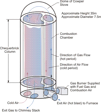
The matter is complicated still further if the process of reversing a regenerator is itself slow. For example, if it is necessary to pressurize the regenerator vessel at the start of the cold period, and then depressurize it at the end of the cold period, as is the case with Cowper stoves used for preheating the blast (of air) for iron-making, then the total cycle time must be long enough for the time necessary for these reversals not to constitute an overlarge proportion of the total cycle time. In this case, the area to mass ratio, A/M for the hot period, A'/M' for the cold period, must be forced to be small enough to generate sufficiently small values of Π and Π' with the longer hot and cold periods of operation necessary.
Fixed bed regenerators operating with hot gas inlet temperatures in excess of 1200°K are fitted with packings constructed of fireproof refractories or ceramic materials of special quality, capable of withstanding the effects of any corrosive materials entrained in the hot gas. Thus, in glass furnace regenerators, it has not been uncommon to use high alumina packings which are capable of coping with the corrosive effects of lime, potash, silica, sodium sulfate and vanadium which can be carried over into the regenerator packing from the glass making process. In Cowper stoves, used to preheat the blast for the ironmaking and zinc smelting processes, the packing is frequently zoned: at the top of the regenerator, materials capable to withstanding the effects of very high temperatures, and further down the regenerator, of high compressive loads are used, for example, silica. At the bottom of the regenerator, it is imperative to provide materials which possess the mechanical strength and volume stability, able to support the great weight of packing above. Different silica-alumina refractories are often employed in these circumstances.
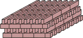
Not only must the materials of the packings be able to cope with the effects of corrosive materials, so also must the geometry of the packings be so arranged that these possibly dirty gases can have free passage through the regenerator. The blocking of the channels must be avoided. In these circumstances, various geometrical arrangements of the refractory materials must be used. "Square chimney" or "closed basket weave" arrangements are frequently used in these circumstances (Figure 2).
It can be arranged that the channels are wide enough to provide free passage for dirty gases but for the packing not to be aligned to form chimney passages: the "open basket weave" or "staggered open basket weave" fulfill this role. The channel width can be as large as 200 mm.
Where the gases are very hot but relatively clean, as in Cowper stoves, hexagonal bricks are frequently used with passages only 50 mm wide. These passages are formed in the body and on the corners of the bricks (Figure 3). In the Freyn chequerwork design, these passages are circular but other shapes are possible. These refractory bricks are arranged in layers in such a way that tubular shaped channels are formed through which the gasses can have a clear passage.
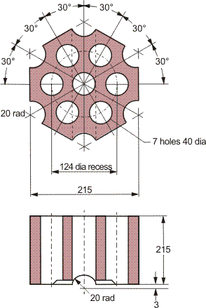
Figure 3. Typical design for the heat storing chequerwork for hot blast stoves (millimeter measurements).
In both kinds of arrangement, the thickness of the packing behind the available heating surface area is determined by the mechanical strength required of the packing as also by the corrosive conditions under which it is must be required to operate. Under severe conditions, thicknesses as large as 200 mm must be used; in less harsh conditions as can arise in the chemical industry, 50 mm thick bricks may be adequate.
There are two significant consequences of these possible packing arrangements. These can be understood in the context of the descriptive dimensionless parameters describing regenerators and their operations.
The reduced length,

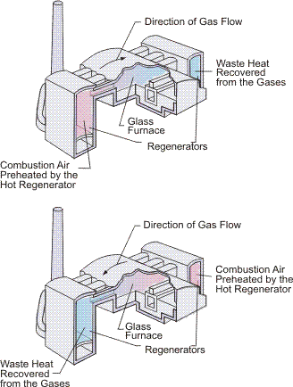
is a measure of the effective heating surface area relative to the heat capacity flow rate of the hot/cold gas. Clearly, the larger the load, MfCp, upon the regenerator, the larger must be the heating surface area, A, to service this load. Indeed, for given operating conditions, the thermal efficiency increases with Λ. High temperature regenerators which employ basket weave or Freyn-like hexagonal packings are physically very large, in some cases, so large that they are built as part and parcel of the furnace with which they are required to operate. This is a consequence of the packing having a low surface area to volume ratio, in the range 20–30 m–1. The large surface area required brings with itself a large volume of packing. Figure 4 gives the layout of a pair of regenerators in a Siemens arrangement, such as a glass furnace. In a Cowper stove arrangement, there are three or four regenerators held in cylindrically shaped vessels which are detached from the blast furnace they are required to serve (see Figure 5). They are still large, perhaps 30 m in height and 10 m in diameter.
On the other hand, the ratios

will be small for packings with a low surface area to volume ratio, as described above. The consequence is that small enough values of Π and Π' can be obtained using relatively long cycle times. It is not uncommon for Cowper stoves to operate with a cold period, P', of between 30 and 60 minutes and a hot period, P, of between 50 and 110 minutes for a three stove arrangement: this includes accommodating reversals lasting 5 to 10 minutes per cycle. Similarly, Siemens type furnace regenerators commonly operate with a total cycle time of about 40 minutes.
Such large regenerators are necessarily expensive. Under high temperature conditions where the gases are relatively clean, it has become common over the last ten years or so to turn to the regenerative burner. Here the regenerator packing consists of ceramic spheres with materials chosen to meet the operating conditions encountered. The spheres are typically 1–3 cm in diameter yielding area to volume ratios of the order of 10 times larger than encountered in the massive regenerators for the glass making furnace, for example. Area to volume ratios in the range 100–300 m–1 yield small compact regenerators. The particular size is determined by the load, Mfcp, which the regenerator is required to support. A bed 0.6 m high and 0.18 m in diameter would not be uncommon, although smaller or larger beds can be used for different thermal loads.
Because the ratios

will be larger for beds of ceramic spheres with a surface area to volume ratio in the range 100–300 m–1, it is necessary to reverse the regenerators far more rapidly than is the case for massive high temperature regenerators. The burners are operated in pairs; during the hot period hot exhaust gases are drawn from the furnace to which the burner is attached, over the bed of spheres. Simultaneously, during the cold period of the other burner fires into the furnace, using combustion air which has been preheated by the regenerative bed. The regenerators and their burners are switched after a period as short as 30 to 180 seconds. The combined burner and regenerator can be made most compact by incorporating a regenerator within the body of each burner unit. A small continuous gas fired furance, used for example in the steel industry for the annealing of strip steel, might incorporate six or more pairs of such burners. They can be operated out of phase in such a way that "apparent" continuous operation is realized by arranging that only one pair of burners is being reversed at any instant.
At more moderate temperatures (400–600°C), it is common to employ rotary regenerative air preheaters. In such Ljungström regenerators, the cylindrical porous packing is rotated around its axis (see Figure 6). The packing materials are often fabricated of steel sheets, notched to form a large number of undulating passages. In this way, turbulent flow of the hot and cold gasses flowing through the regenerator is promoted, thereby improving the heat transfer characteristics. The metal sheets are arranged radially in removable units holding several such sheets, thereby facilitating rapid and simple maintenance.
Such metal sheeting provides a high area to volume ratio, in excess of 200 m–1. Nevertheless, they must be constructed in such a way as to be able to withstand the temperatures involved as well as possibly corrosive operating conditions. Where, for example, the hot waste gases have a high SO2 content, a vitreous enamelled heating surface can be employed to protect the steel packing at operating temperatures below the acid dew point of such gasses.
Even higher area to volume ratios can be achieved by constructing the regenerator of an assembly of sector shaped sections of a knitted mesh of wire of another material, depending on the temperature and other operating conditions. For hot gas entry temperatures of 400°C, stainless steel mesh can be employed while for temperatures of up to 800°C ceramic or alumina fibers have been considered. Other prefabricated heavy duty ceramic packings can be employed in regenerators required to withstand hot gas entry temperatures of 800°C or more: here the packing might consist of a honeycomb of ceramic material arranged as alternately flat and wave shaped layers. Such constructions realize the high surface area to volume ratio necessary to achieve compactness in regenerator construction and, at the same time, allow for a free passage for the flow of the gasses through the regenerator. They are also robust enough to survive the tough working temperatures and harsh operating conditions.
Again the ratios

will be large for the rotary regenerator packings described above. It is not uncommon, therefore, for the packing to be rotated at 2–3 revolutions per minute, yielding hot/cold periods of 30 seconds or less. Small values of Π and Π' are thus generated, thereby facilitating regenerator efficiencies of 80% of more to be realized.
The operation of regenerators at low (ambient or even lower) temperatures permits a good deal of flexibility in the choice of packing materials. Rotary regenerators for air conditioning applications employ a variety of packings which include a polyethylene terephthalate film and corrugated, knitted wire mesh. Such packings are wound round the spindle of the rotor yielding heat wheels of varying diameters, from 1.25 to 2.5 m. Corrugated aluminium sheets are sometimes used as are various honeycomb arrangements (see Figure 7).
A variety of packings have been developed to recover both latent heat and specific heat from one of the gases. Included in these are packings which are nonmetallic and fibrous: they can absorb moisture on the one hand but are inert to bacterial contamination on the other.
For very low temperature operation, fixed bed regenerators are frequently used where packings consist of beds of basalt or flint chips, or simply gravel. Corrugated aluminium sheets are sometimes used where corrugations run in alternate directions between the sheets which are laid on top of one another, generating fine, intersecting channels for the free passage of the gases. Such arrangements of aluminum sheets can prove to be prohibitively expensive, however.
Nomenclature
A heating surface area exposed to heating/cooling fluid m2
as thermal diffusants of packing m2/s
p specific heat, at constant pressure, of fluid J/kgK
L length of regenerator from fluid entrance to exit m
M mass of packing "behind" the surface area, A kg
Mf mass of gas resident in the voids of the packing kg
 mass flow rate of fluid through the regenerator kg/s
P duration of hot period s
P' duration of cold period s
Tf temperature of the fluid K
Ts temperature of the solid packing K
t time s
y distance from the regenerator entrance m
Greek Symbols
α surface heat transfer coefficient W/m2K
 bulk heat transfer coefficient W/m2K
δ thickness of the regenerator packing m
κs thermal diffusivity of the packing m2/S
λs thermal conductivity of the packing W/m K
Ω dimensionless duration of hot period —
Ω' dimensionless duration of cold period —
REFERENCES
Bahnke, G. D., Howard, C. P. (1964) The effect of longitudinal heat conduction on periodic-flow heat exchanger performance, ASME Trans, series A, Jour. Eng. for Power, Apr 1964.
Hausen, H. (1929) Über die Theorie des Warmeaustauches in Regeneratoren (The Theory of Heat Exchange in Regenerators), Z. angew. Math, Mech., 9, Jun 1929,173–200 (RAE Library Translation No. 270, September 1948. W. Shirley), Jun 1929.
Hausen, H. (1942) Vervolistandigte Berechnung des Warmeaustausches in Regeneratoren (Improved Calculations for Heat Transfer in Regenerators), Z. VDI-Beiheft Verfahrenstechnik, 2, 31–43, Iron and Steel Institute translation, dated June 1943.
Hausen, H. (1976) Heat Transfer in Counteijlmv, Parallel Flow and Cross-flow. English Translation edited by A. J. Willmott, McGraw-Hill.
Razelos, P., Lazaridis, A. (1967) A lumped heat-transfer coefficient for periodically heated hollow cylinders, Int. J. Heat Mass Transfer, 10, 1373–1387. DOI: 10.1016/0017-9310(67)90027-0
References
- Bahnke, G. D., Howard, C. P. (1964) The effect of longitudinal heat conduction on periodic-flow heat exchanger performance, ASME Trans, series A, Jour. Eng. for Power, Apr 1964.
- Hausen, H. (1929) Über die Theorie des Warmeaustauches in Regeneratoren (The Theory of Heat Exchange in Regenerators), Z. angew. Math, Mech., 9, Jun 1929,173–200 (RAE Library Translation No. 270, September 1948. W. Shirley), Jun 1929. DOI: 10.1002/zamm.19290090302
- Hausen, H. (1942) Vervolistandigte Berechnung des Warmeaustausches in Regeneratoren (Improved Calculations for Heat Transfer in Regenerators), Z. VDI-Beiheft Verfahrenstechnik, 2, 31–43, Iron and Steel Institute translation, dated June 1943.
- Hausen, H. (1976) Heat Transfer in Counteijlmv, Parallel Flow and Cross-flow. English Translation edited by A. J. Willmott, McGraw-Hill.
- Razelos, P., Lazaridis, A. (1967) A lumped heat-transfer coefficient for periodically heated hollow cylinders, Int. J. Heat Mass Transfer, 10, 1373–1387. DOI: 10.1016/0017-9310(67)90027-0
